timetrack
Digital time keeping system with both a web-based calendar entry and a kiosk based badge entry interface
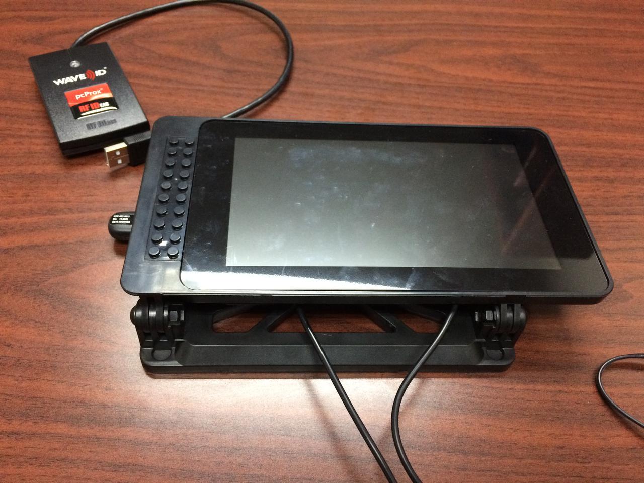
TimeTrack Raspberry Pi
At the City of Bloomington, Indiana, we use a number of different solutions to keep track of hours for employees. We have some employees who utilize a paper based punch clock, but we want to automate the process of digitizing those hours.
We’re using a Raspberry Pi and touchscreen to serve as a simple kiosk terminal. This is set up to show our web based timeclock application. Employees can use their RFID enabled badge to clock in or clock out of the system.
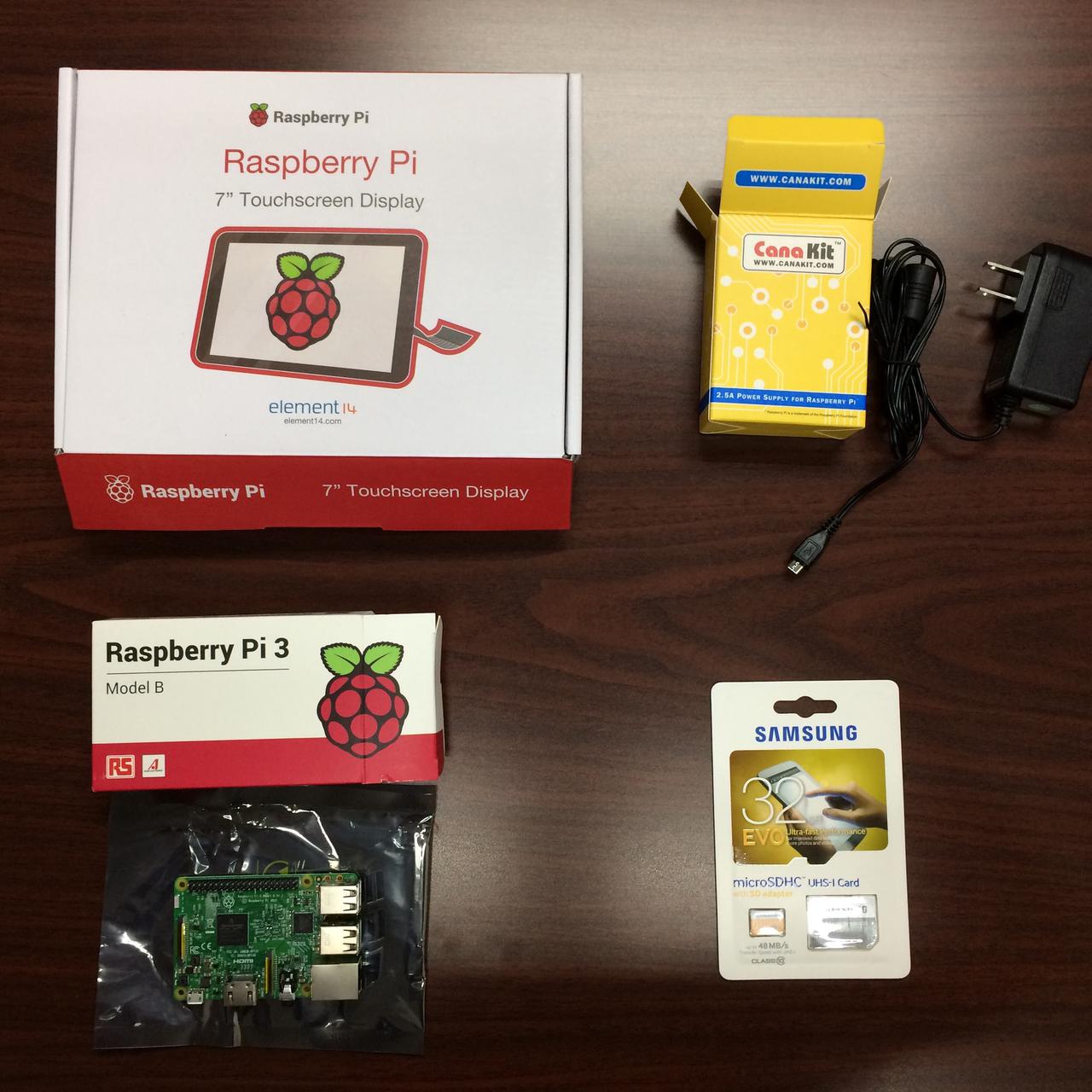
Parts list
- Raspberry Pi 3 x1
- Screen x1
- Case x1
- RFID Reader x1
- Power Supply x1
- Memory Card x1
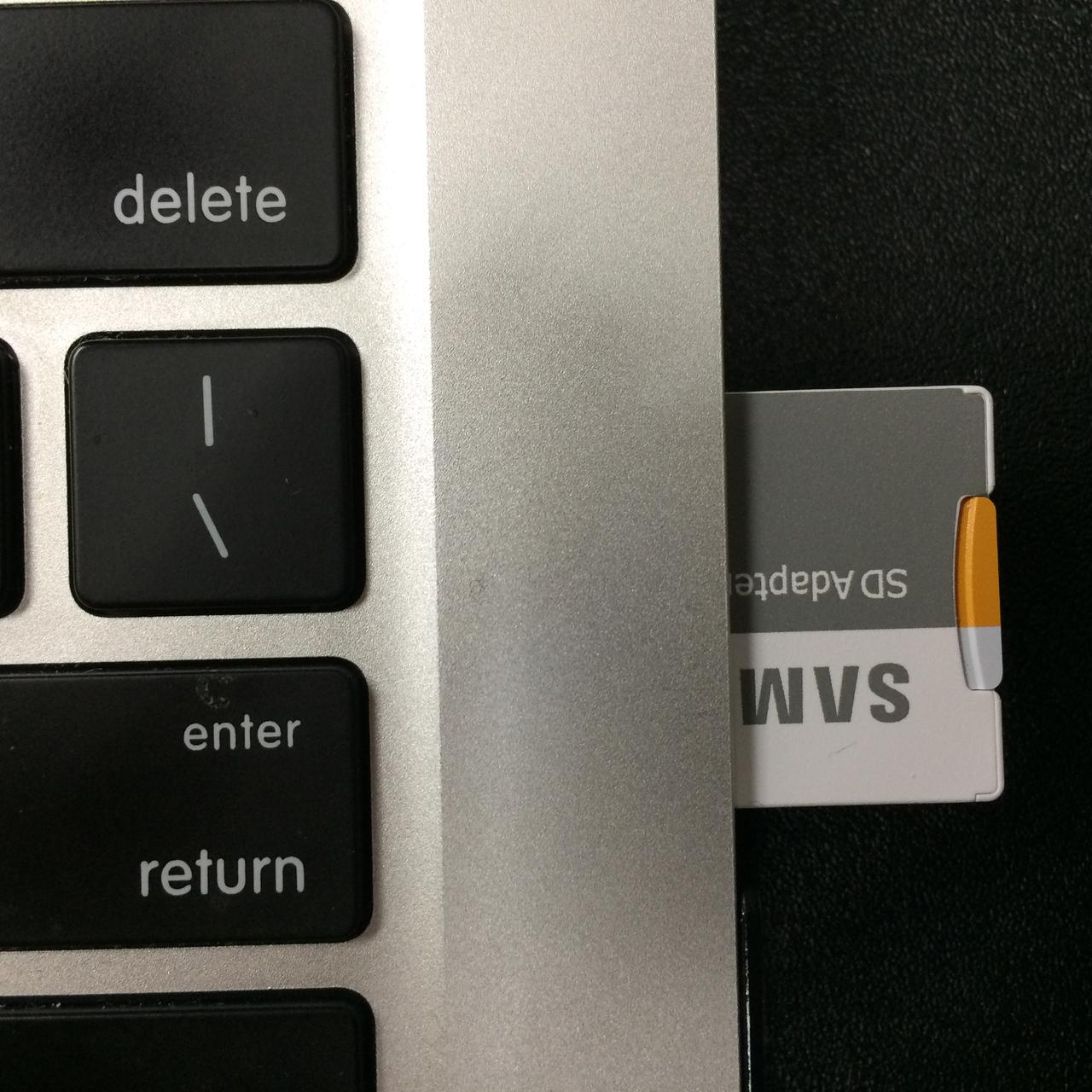
Flashing the image
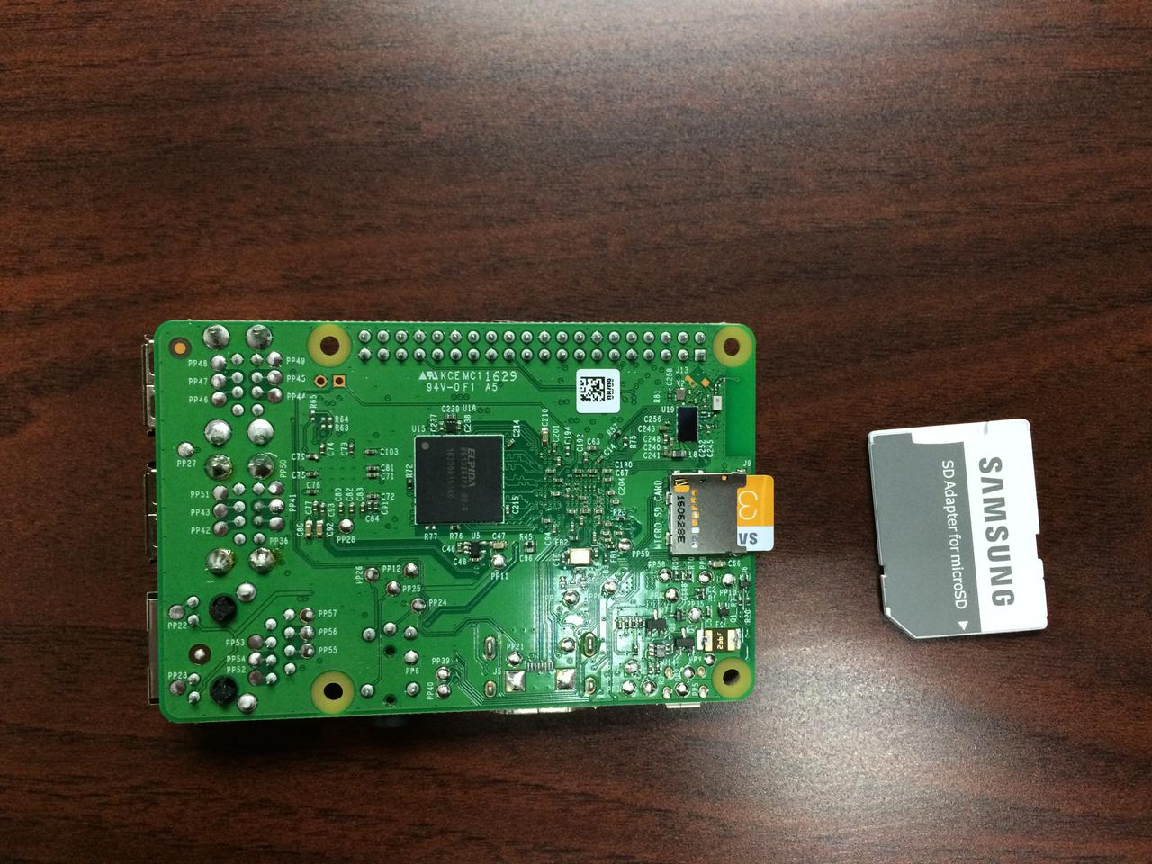
Start by opening the memory card and inserting it into your PC/laptop’s reader.
We will be using RDS (Raspberry Digital Signage) to run our kiosk, so download and extract it. We are also using the Donator’s version, which allows for additional options in the system and kiosk areas.
Download: RDS
This guide is written as if your intent is to flash this image to many different SD cards, and as a result some of the steps may be more complex than if you were just doing it for a single device.
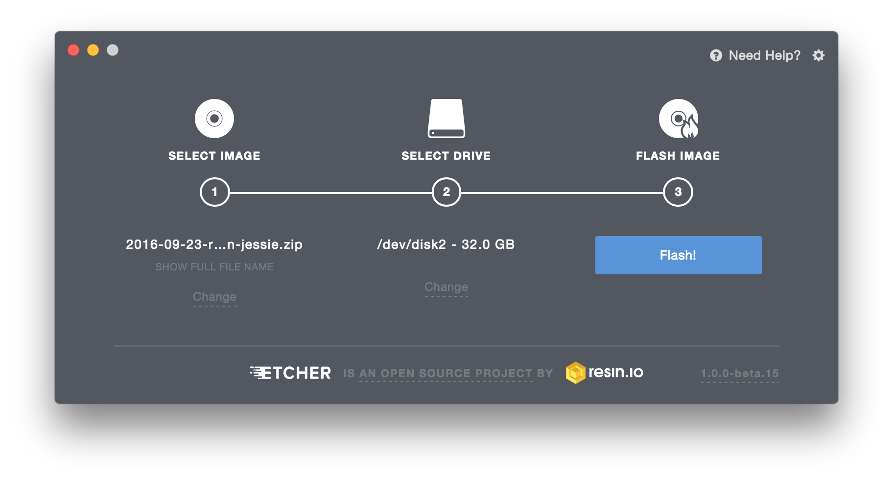
Imaging software
Next up is to transfer the extracted image to the SD memory card.
Etcher is a nice multi-platform piece of software for easily transferring images. Win32DiskImager is another nice application for Windows, which can also read back the image from your card when you’re done modifying it.
For Linux/macOS you can also just used the dd command to read/write images.
Download: Etcher.io
Download: Win32DiskImager
Flashing
Once flashing is complete, eject the Micro SD card from your system.
Assembly
Insert the Micro SD card from the previous section into the RaspberryPi.
Next, install the Pi in the case and install the touch screen too. This is a good video to follow:
Connecting the Ribbon Cable
One aspect that was glossed over is how to connect the ribbon cables. Be sure to pull out the black plastic tab that keeps the cable secure first:
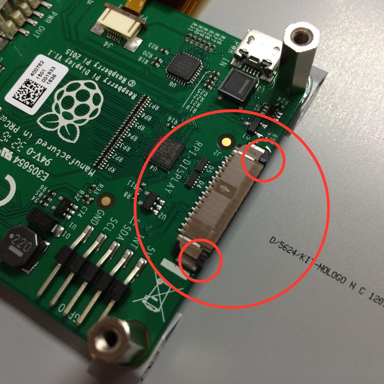
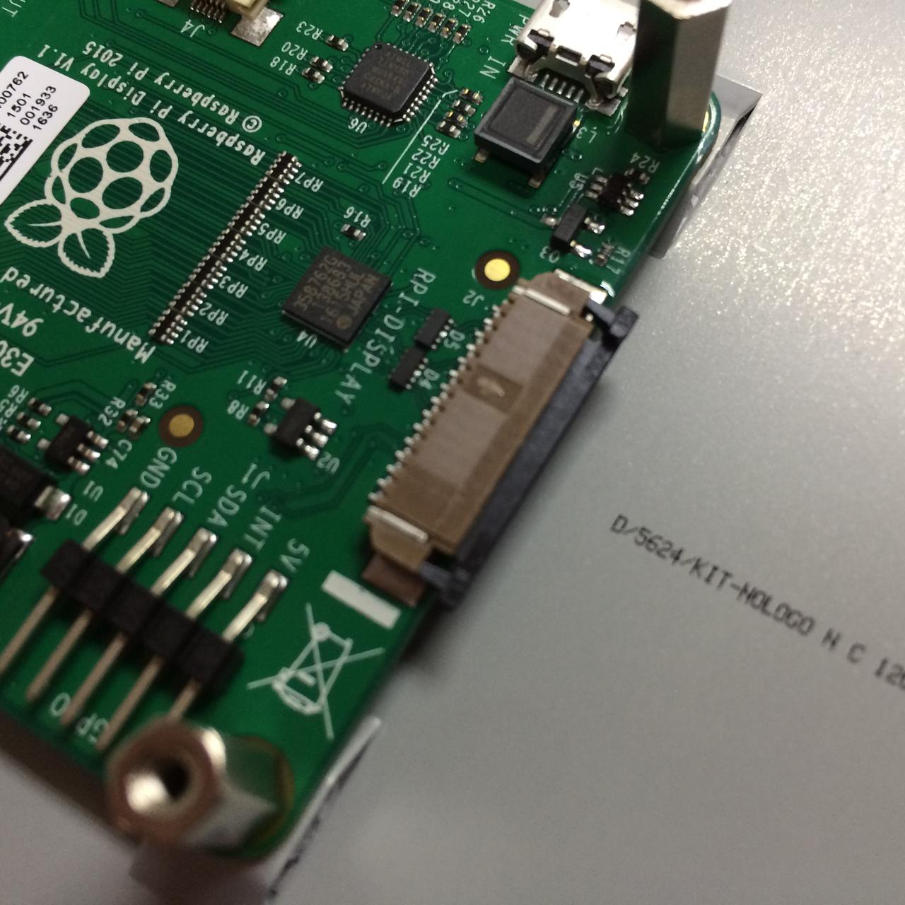
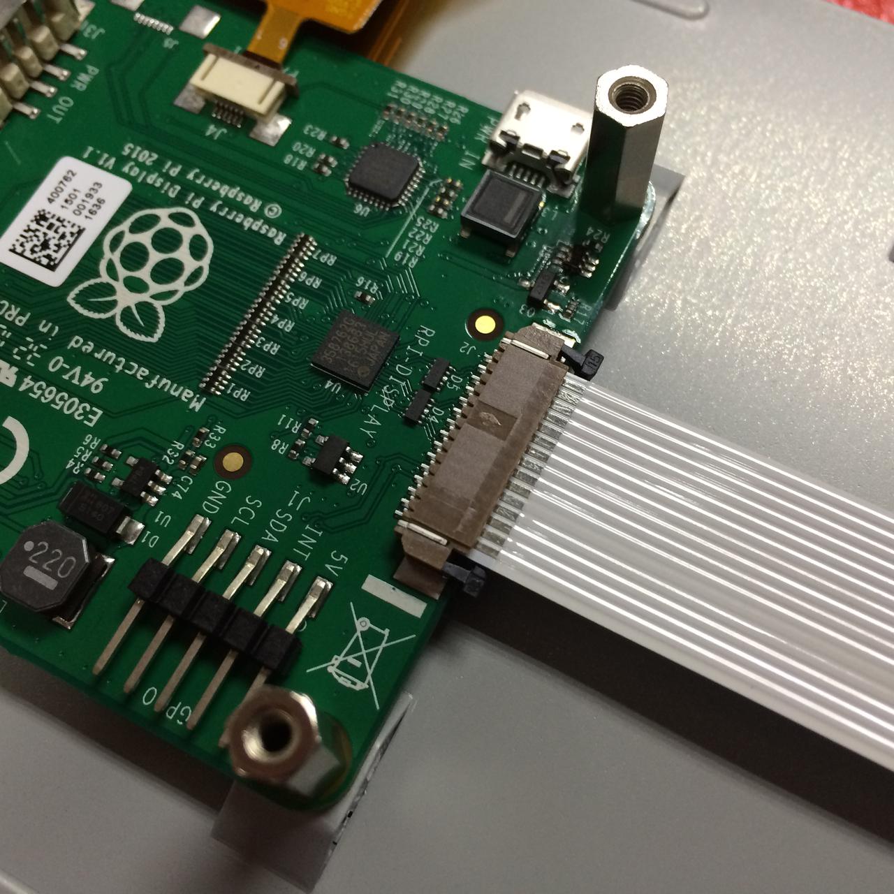
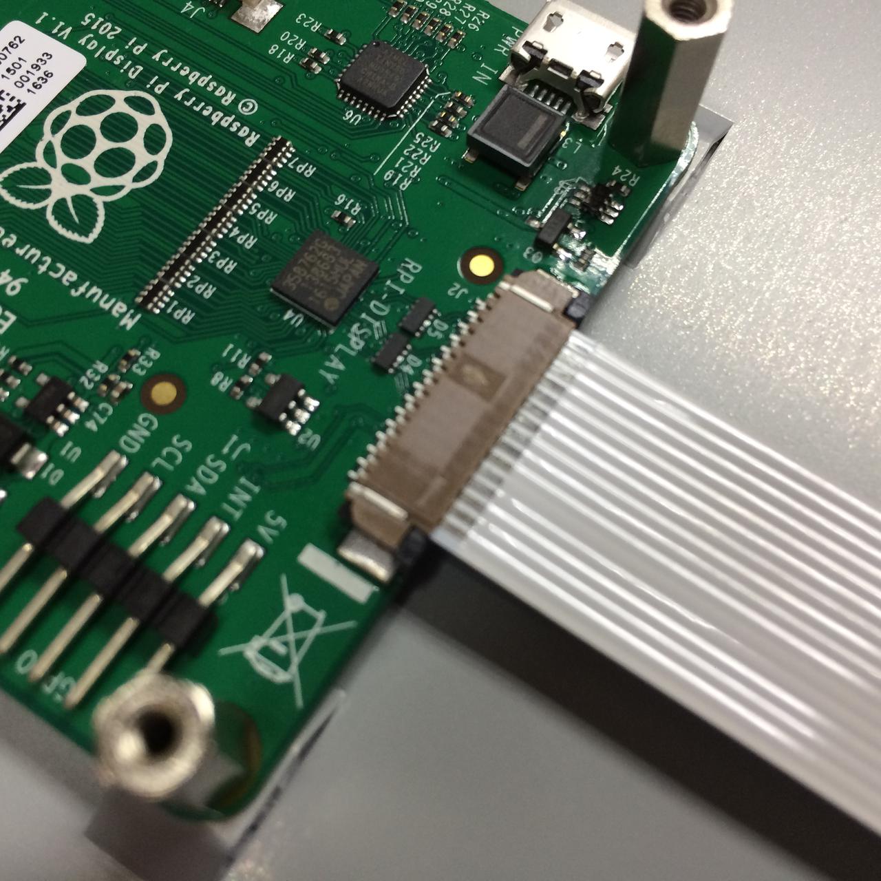
Once you’ve done your first build, it’s easier to do subsequent ones.
At this point everything should be assembled and hooked up, including “Y” USB B cable for power.
Plug in the usb RFID reader
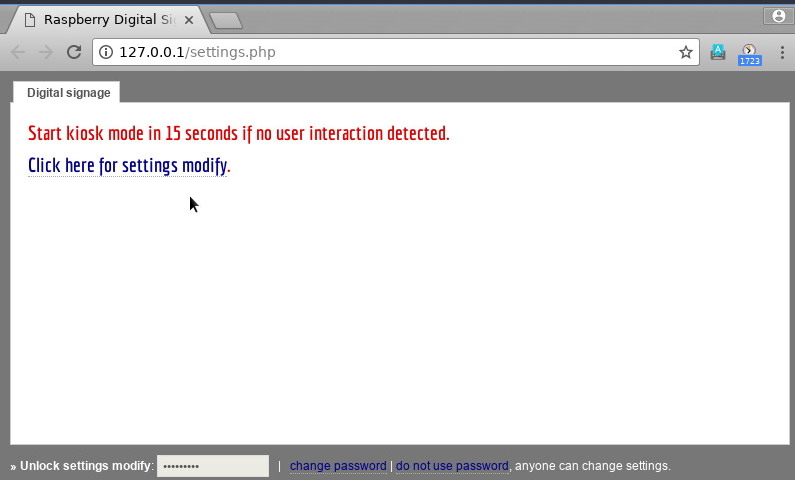
If all goes well, plug in the power supply to the “Y” cable and the machine should boot up. During the boot process, a brief 15-second window will be given to enter into the configuration menu.
Configuration
Configuring Networking
If the machine is plugged in via Ethernet, RDS will use DHCP by default and assign an address. If you wish to use WiFi, leave the cable unplugged and a menu will appear with options to type in your wireless network options.
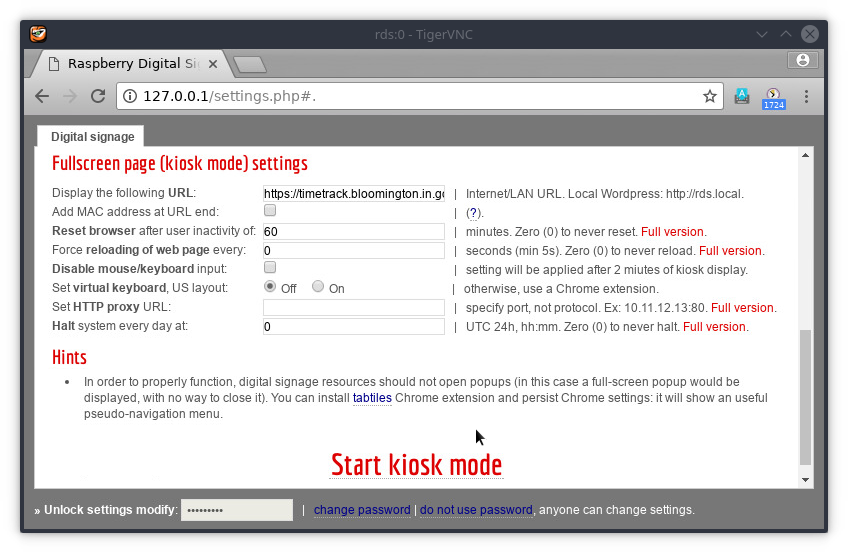
Setting up Basic Options
If you click the option to enter the setup during the 15-second boot window, you will be taken to a screen with several options to control how the kiosk behaves.
Be sure to change the password using the link at the bottom.
Fetching MAC info
Next, open a SSH session to the Pi. The IP address should be displayed onscreen. The username is “pi” and the password is whatever you set it to in the options. Run the following command:
ifconfig
Note the network interface’s MAC address (“HWaddr” in output). If you’re using the wired network connection, it will be in the “eth0” section. If you’re using the wireless connection it will be in the “wlan0” section.
At the end of this process, send the MAC address and physical location to the system administrator so they can configure the right address in our DHCP server.